

Weekly Breakdown
Week 1
Contiplating
Both groups brainstomed new sensor ideas, elected team leads and team names
Week 2
Week 3
Decideing sensors and expiraments
More time was spent deciding on sensors, there was an issue with the sensitivity of our flight data recorder and trying to keep below the weight limit.
Sensors arrived
Both teams have recieved all their sensors and started figguing out how they work.
We got the 3D camera to work but found out it was more difficult to get our geiger counter to work then we thougt.
Making sensors work
Our team assembled and test some of the sensors that we recieved.
Testing and assembling sensors
Sensors finally started working, tests and trouble shooting where highly successful.
Sensors finally start working!
Week 4
Week 5
Week 6
WEEK 7
Calibration and programs
Genaro got his sensor working! I (Rik) tested and calibrated the RF receiver. plans for payload started!
WEEK 8
WEEK 9
Still messing with sensors
2 steps back...
We've been Sparbered!
Payload construction at home
I (Rik) took the materials needed home to construct the payload.

Both teams hurry before the end of the day to complete their payloads.Our team completes our payload despite more curveballs from Rick.
WEEK 10
Stress Tests
Paylaod
Hand in
Week 11
A successful launch and we got data!
Launch Weekend
Week 12: data review
Week 13:
Symposium power points
Week 14:
Symposium
Week 15:
Final presentation practice
Week 16:
Final presentation
Fallowing weeks
Final Presentation
and
Symposium

Week 1
Both teams start the week with Ideas...
This week we worked on taking apart the old payload from the previous semester. Rik, Jenaro, Juan, and Shelby got together and made decisions on what to add to our payload. Our decisions where as listed below.
-
RF sensor that detects short-band radio frequencies.
-
2 peep marsh mellow experiments; One peep is going to be outside the payload dangling from a string to allow us to see how much it expands. The other will have a temperature sensor inside it to see how much insulation the peep offers.
-
We will also send up seeds and have control of seeds grown already to see the effects of radiation on the plants once they return.
-
The last experiment is a yeast-based expirament where we will use a pressure sensor, crushed water, and yeast to find out how much Carbon dioxide is created.
Pictured Below is the 2 teams and the Professors planning and deliberating


After this, we then discussed the team lead, which will be Jose.
Then we discussed the team name. We are still trying to decide what that is...

Week 2
Both teams discuss sensors and make purchases.
This week both teams concluded decisions on sensors and filled out purchase forms. The sensors we have decided to use are as stated below:
GPS

Temperature sensor

RF Dector

Runcam HD

Plants (vine) Wisteria
Geiger Counter


LG Camera
Pressure and Accelerometer sensors


Problems already start to arise
We found out that the RF receiver gave out too low of voltage for the flight data recorder can detect, so we need an amplifier!

We discussed this issue for a few hours and found out we need the proper antennae and cable to get this to work properly and bring it to the specifications for the flight data recorder.

There is a way to modify the board for the GPS
If we decide to install the GPS on our board, we will need to modify our Flight data recorder to be able to use it.
Rick showed us how to do this by allowing us to barrow his board.

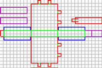
I (Rik) updated our system block diagram
The system block diagram was updated to show the changes to our virtual payload and sensor connections. Basically, I removed all the sensors but the temperature sensor and connected the RF sensor. The board seemed so bare without all it's senssors from last semester.

Week 3
Both teams now have their sensors
Both teams have received some or all of their sensors and started preparing them for the mission. Everyone started working on the sensors. Many things were learned in the lecture.
We discussed how to do the peep test, which concluded on how we will attach the peep to our payload via a string. The peep will be affixed to a cardboard circle and a string, that is attached to the payload. The Ozone sensor was scrapped, due to operating and humidity requirements not being met.
There was a discussion of having 3 growth tests for the fine seeds, one test will go with the payload, another will go through the freezing process as if it was on the payload, and then a control grow normally.
The things we are still waiting for:
The post-processing of the 360 camera so we can get stable video.
The Geiger counter, amplifiers, and power supply are in transit.
Rik Worked on the RF Receiver and found out that we needed an amplifier to detect the signal in the video below.
Rik found a 1.5 to 10,0000 amplifier and had to also buy a special power supply.

I (Rik) wanted to mention the other team's sensors. Especially since the spectrometer was my idea and I gave it to the other team lead this semester, I really hope they get it to work and get to fly it in a couple of months.
Spectrometer

Accelrometer

They also will run a GPS, Geiger counter and a camera
Finally, Rik and Genaro updated out system block diagram.


Week 4
Working on sensors and getting the camera to work
There was some discussion about the sensors, where we need more information about the CO2 sensor.
We also added and moved temperature sensors to a total of 3. One temperature sensor will be used within the payload, one to take temperatures of the seeds, one on/ near the camera, and one outside the payload.
We also decided to add a Pressure sensor.
Jose gave out plans to complete the sensors within 4 weeks.

The updated system block diagram reflects the changes stated.
Below are videos of us trying to troubleshoot the Geiger counter and what was going on.
360 Camera working!
Below is a video from the 360 camera working, although we have to get past all the bugs still with this, at least we got something working on our payload now that was not from last semester.

Week 5
Sensors actually start working!
Today Both teams hit the road running! All our sensors and parts arrived during the past week, and we are ready to try to get things working. We got most of our sensors on breadboards, a few worked, and a few did not.
Shelby found that our Geiger counter was DOA. It did not work since arrival. I (Rik) had read the documentation on the Geiger counter and noted that it was sensitive to vibrations which are not good since our balloon will see a lot of vibrations, especially when the balloon pops. The RF receiver worked with a signal of 1.2 volts output. We also did temperature and pressure calibrations, And Jose was trying to get the 360 camera to work remotely. Below are videos of our team working on all these things.
Below is a system block diagram that I (Rik) had to create for Rick to make him happy and allow me to start working on the RF sensor. I did so, but he made me look for all sorts of data sheets that were very confusing and led us on a wild goose chase for several hours. After Rick gave up and went to Dr. Frank for help, Dr frank looked at the diagrams I made before this wild goose chase and told me to go ahead and build it on the breadboard, wasting 5 hours of my life.

While I worked on the RF reciever, the team did well getting their stuff done. Genario was successful in recalibrating the temperature sensors to their new ports, and making sure the accelerometer and pressure sensor worked.
Below are his data graphs.
(First set of graphs are the calibrating the Temperature sensors. One does this by taking the room temperature for control. Then put the sensors in a cold environment with the thermometer and get low, then you do the same with a hot environment. Finally, you use a formula to get the slope of the line and use that in the calibration to get a precise reading.


Shelby worked on the Geiger counter, and Jose worked on the 3D camera.
Also, a side note, Kevin tried his first Peep in memory of Bob Born, who invented peeps and died last week.

A Change in heart. erm.. Seeds
Because the old seeds took too long to grow, Shelby found something that grow much quicker and would be more viable for experimentation time constraints.
He picked these because they only take about a week to germinate and take only about two weeks to mature enough to eat.
Week 6
Sensors finally start working!
There was a reason the balloon pop background is here. It's because we were able to get some sensors completed!
The first success was Genario's code for his CO2 sensor. He indicated this in his slideshow for the team update each week.
The other successes were later, but there were also failures and lots of work.
Let's go to the system block diagram, where we will see what sensors and updates we have.

First, let me point out the peep Dr. Frank wanted us to put a Peep in the system block diagram. Notice anything missing?
Your right! the 360 camera is gone! Late that day, we had lots of issues with it. Jose was supposed to be testing and prepping the camera, but he did not, so he tested the camera today and found out that it only runs for about 20 minutes. They did state that the camera's system which purposely does this per its programming and that he can hack the software to stop it from doing this. I purposely updated the System block Diagram to show it missing because I knew it would have issues.
Another thing may go missing soon.

The CO2 Sensor
Problems surfaced a couple of weeks ago when we received our sensors in the mail, and Genaro showed me this sensor unpackaged. It was a surface mount sensor, and we did not have a PCB to match that, nor did he have the experience to do it himself. I (Rik) was the only one with the know-how to do the soldering. I (Rik) soldered on 14-gage stranded core wires onto pads as small as a tip of a pen to have Genaro break them off again!
The problems did not stop there.
Later we learned about
The programming needed to get this to work with our Flight Data Recorder. This sensor communicated with I squared C.
But upon closer inspection, we noticed that the wires were soldered in the wrong locations (remember someone had to solder wires back on, and it was not me). So today, I (Rik) removed them and soldered on new wires in the correct positions.
But something happened while trying to strip the ends so I could solder the wires to the protoboard shown above.
One wire ripped off the chip and ripped the entire pad with it. Rendering the sensor is useless. Glad we had a spare!
We dug out our spare, and I soldered on even more new wires on that one. This time I went to solid core wires I found in another classroom. I also pre-stripped the ends, so pad removal will not happen again. We successfully got it soldered together and safely on the protoboard at last! (stop freaking out about anyone touching the sensor Genaro, the Board is great protection to shock resistance, and we should be fine).
But wait! there is more! If you call now, we will send you more problems for free! Free shipping and handling, and you can give your problems to your friends and family too!
Yep, there were even more problems.
Genaro had me wire up this to a breadboard to test if it worked. I added a lowpass filter to the power in and followed the diagram from the material Genaro provided, which showed shunt resistors to the two data pins but no value.
I dug out potentiometers to try to find this mysterious value. I found that to get anything out of this thing was a high value 10M ohm resister, and it did not look good. The oscilloscope showed smooth flat lines, not the expected wavy data like the ones I was expecting from a digital device. I tried everything from checking voltages with a multimeter to replacing all the components on the breadboard, but nothing. I told him I did everything to my knowledge. As a last resort, they asked Dr. Frank, who told them to try to hook it up to an Arduino. Genaro ripped off just the sensor from the breadboard, forgetting the low pass resistors and the pull-up resistors were still on the breadboard. I just looked at him and said what about my filter and resistor? At that moment, I had to go home, it was well past that time, and I stayed well past the time I was supposed to.
You will see an update about this sensor next week!

The Geiger counter
Shelby knew what he was doing, had everything out just before I did to work on his sensor and did not need help to get it working. He was smart to buy a plug-and-play sensor, unlike the radio receiver or the CO2 sensor. And that was pretty much what he did. He plugged it into a pro-micro and then got it to work within an hour, he was receiving data and partially calibrated the sensor before the end of class, and he and Jose were long gone before we got both the RF receiver and CO2 sensors hooked up and tested.
The Rf receiver
There was no question that the RF receiver sensor worked because of an insanely smart engineer who designed it with an orange LED that lights up when the sensor is operating properly. The data output signal was too week for the Fight Data Recorder to detect. So we had to build an Op-amp amplifier and a big one too!
We needed to enhance the signal by 1000000 (one million) times. The amplifiers where available everywhere, and it was easy to find a Three pack of 1000x Amplifiers cheap from a supplier that was not Amazon. We also needed a small power supply that generates negative voltage to help the amplifiers do their job. That was a little harder to find, but I found a good one and ordered a few.


Disclaimer
I (Rik), was put in charge of the Rf receiver, and I had many issues trying to get help on it (as you saw last week); this actually happened the week before when I went totally ignored. The week before that, I was tasked to get the Geiger counter working, and I did. I also have been tasked to assemble and troubleshoot all our sensors so far, which slowed me down on my project, but somehow I finished it today! The day I decided would be the do-or-die day for my sensor.
After last week, I put in a couple of hours Thursday towards my amplifier issue. Rick instructed me to tune the amplifiers by bringing in a stable low voltage, but of course, he did not tell me how. I learned how to make a voltage divider out of two resistors tied together, the larger value going to the ground, and where the two meet is a tiny voltage I can use. I used a 10K ohm and a 10M ohm to get about 20 millivolts which were 8 millivolts higher than what my RF receiver put out on the data pin. I found that, I had to assemble low-pass filters for the negative voltage because the power supply made noise. I also messed up and fussed with the wiring until it worked. Once I had it working- I hooked it up to an oscilloscope, zoomed in as far as it could go to see the noise, and tuned it all out. I noticed a click in the second amplifier's zoom pot when doing this and later realized that it caused the second amplifier to fail (glad I had 3!).
Friday; (when all the other sensors were made, worked, and tested).
While I worked on my project, I also worked on Genaro's CO2 sensor. I came in running, knowing what needed to be done.
I added a few more resistors to smooth out the noise (2 47 ohm ones and replaced the capacitors for the low pass filter from 220 uF to 100 uF ones because it was doing too good of a job and cleaning out my signal too. I also noticed if I had the pots on the amplifiers turned too far, they would block out the signal. I decided to amplify it to 2.5 volts to leave room on the pots, so I would not have this side effect. I quickly replaced the broken amplifier with the third one and was detecting a signal; that was strong enough for the Flight Data Recorder to detect. Once I saw that I got a protoboard, I soldered on the components, and wired it up the way I had it on the breadboard. It was way past the time I was supposed to leave. (I also was still helping Genaro with his sensor during the entire time). When I left, Genaro was still there.
During the week: Genaro came to me on Tuesday, and I helped him set up his CO2 sensor and connected it to an Arduino microprocessor. But it looks like the software was not functioning correctly. We will work on that next week.
Also, Jose updated us on the 360 camera's progress. The camera will not work for our mission, as he was unable to get it to constantly record beyond 20 minutes.
I know I have not tested the sensor yet while it's all soldered up on the board, so I'll give you an update next week!

Week 7
Testing and calibration of RF sensor, Geiger counter, troubleshooting CO2 sensor. 360 camera gone.
Today was a successful day! I (RIK) tested the RF receiver and was successful as well as Genaro got the CO 2 sensor to work.
Here is the data for the RF receiver during testing.


This data to the left shows the RF sensor is working properly in the lab.
This graph shows me transporting the device to the fridge. the fridge was successful on blocking out 2% of the signal, which shows success.

Genaro Worked on his CO2 sensor, and after a while, got it to work after getting help from Dr. Frank.
After that, we started talking about how to hold the peep.
Below are some videos of what the team did.
Dr. Frank had a question about the camera's focus and the peep, this is the peep about 6 inches away.

Week 8
Rick is back! more wild goose chases!
Team gets nothing done...
The morning started with a long slideshow where Rick Sparber questioned how I (Rik) built the amplifiers and sent me on another goose chase to find the fabled diagram of the amplifiers (we searched for these during the first weeks and were unsuccessful. I found some posts online that showed me how to wire the amplifiers, but this was not enough for Rick.

I was actually able to find them quickly.
it must have been a key word or something! But after he inspected these, he still was not happy with how I set up the amplifiers. (even though they worked and even showed 0 volts disconnected)
He told me to short S+, S-, and Ground on each amplifier and make sure the output voltage is Zero. I will say it did output Zero volts. After following his instructions for the first amplifier, I noticed that the amplifier had stopped working. I thought it was a broken pot and switched it out with the spare we had. I tested the other two and noticed one amplifier was really hot, and it stopped working.
Payload design
At least something was done! We designed our payload!
below is my rough drawing, and below that is a 3D cad version of the same drawing.
The hole in the slanted area is for the camera, the small hole on the top is for the lamp rod, and the large hole on top is for the petri dish.
The whole back side (out of view) will be a door that can be opened.

The rest of the team worked hard
Genario worked on his CO2 sensor but couldn't get it to work today. This is not a good sign for that sensor. Shelby went and calibrated his Geiger counter. Jose worked with the run cam and made sure it worked.


A day of frustration ends with us back Five steps
I wanted to construct the payload housing today, but instead ended with one sensor not working (the RF receiver) and down the CO2 sensor.
Thanks to Dr. Franks's kindness, He stayed after Rick Sparber left after finding out what Rick did to me and my RF receiver's amplifiers. He stayed and made an amplifier out of an op-amp (he even tested what Rick wanted to test with my amplifiers, but his amplifier is designed for it. I (Rik) took the breadboard home with the circuit on it, along with the material for the payload housing as Launch will be the weekend after Spring Break.
Here is a System Block Diagram displaying the most updated payload buildout. (notice the RF receiver).


Week 9
I (Rik) worked on the payload during spring break.
I (Rik) was tasked to get the payload housing completed and to get my RF receiver working again.
Below is the work I did on the RF receiver's amplifier and on the payload housing.


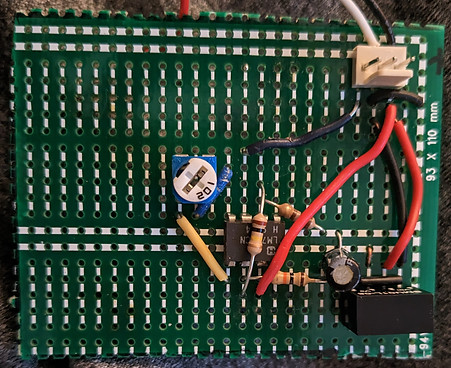
Circuit diagrams
The first step after getting the op-amp was to draw a circuit diagram. Dr. Frank drew this one on the left. It was a bit difficult for me to understand without drawing my own (below). Then we put it on a breadboard, tested the circuit, and brought it close to 0 as we could by turning the pot; after that, we tested it with the RF receiver.

Time to put it together!
Now it is time to populate my protoboard with wires, resistors, capacitors, the power supply, and the op-amp.
Below are the 2 pictures I took of the work on the left is incomplete, and on the right is complete.

Payload housing construction begins
After I (Rik) completed the RF amplifier, I started work on the housing. After that, I started installing the sensors into the housing. Below are the pictures.


Now that I have fitted most of the sensors, I pulled out the FDA and got the first tests for the RF sensor. I did it this way, because I wanted to see how much space the large things would take.
Testing and installing the RF sensor
I set aside the sensor to get tested later and noticed it was not working. I quickly began to troubleshoot the build, starting with the sensor. Its light was on, so I knew it was getting power. So I knew it was a problem with the new amplifier. I took my volt meter, probed each connection, and noticed immediately that the 5V and pin 7 did not match. The 5 volts were going to the end of the wire on the board, yet the voltage was not reaching the chip. Hmmm. I quickly turned over the board and then noticed the problem, a broken copper track! I repaired it using the technique I taught in the same class last semester.

Repair done, Amplifier works!
Now that testing shows proper voltages, I am ready to install this sensor into the payload. I thought it would be best to install it in the furthest part of the payload giving the other team members better locations to place their sensors.
I placed the sensors in the tight back corner with the pressure and accelerometer. I placed the switch back there, allowing us to have all the sensors in a cluster.


Genaro Stops by and visits Friday during spring break!
Fortunately, I was not alone with work on the payload during spring break. Genaro did his homework and was able to complete his sensor after coming over for a visit! We even got it working, finally!


Outside help
Genaro and Jose got outside help with the CO2 sensor's software issues it had.
Their pictures are below
Nicholas Stine Luis Fernando Arce Gutierrez

Help with Code
Nicholas Stein and Luis Fernando Arce Gutierrez played a vital role in the coding regarding the CO2 sensor. The CO2/ temperature/ humidity sensor was digital and needed code that used the Softwire library via Arduino IDE to allow for communication between the SDA and SCL pins on the sensor and D14 and D15 pins on the main Flight Data Recorder. We ran tests on an Arduino board with SDA and SCL pins before adding it to our Flight Data Recorder. Initially, the original code for the CO2 sensor we had did not work. Furthermore, 2 codes straight from the spec sheets with appropriate adjustments did not work either. Fortunately, Nicholas and Luis helped. Luis helped first. On the spot, Luis analyzed the Softwire library and made code with the least amount of lines. The sensor finally worked on the Arduino Board, and in theory, we had to plug into our Flight Data Recorder and change the pins on the code. However, we were ready to put the code on our board a week before launch, so the instructor told us it was far too late to put it on our board without risk to the mission. We decided to run the CO2 sensor on the board we were running the tests on instead of the main Flight Data Recorder, but it was going to require software. When all hope seemed lost, Nicholas was willing to help us out 6 days before launch. He was very kind and made time to help out. He was able to help with expanding the code we already had (see the code pictures on other pages). He made the main code that would read CO2 and Humidity Data (not temperature because it would result in fewer data points, and we already had a temperature sensor on board). Afterward, he made code that would extract data from the Flight Data Recorder post-launch as well as code that would delete any existing data on the EPROM. In the end, we had three scripts, one that deletes data, one that reads data, and one that extracts data. The result, was a successful launch and presentation thanks to Nicholas and Luis's on-the-spot thinking and programming. Below you will see the CO2 and humidity data.

Week 10
Both teams race to get payloads complete, we complete our payload!
Today was a day of high activity where both teams rush to get things soldered and completed. The late comers were Shelby's Geiger counter and Genaros CO2 sensor for our team. The other team had multiple sensors to complete. They were unable to finish the payload beforehand. Finally, I was able to fit all the sensors on board the payload.
There was a bit of pushback from Rick about the RF sensor, but we tested it to the degree of his liking.
Work on the payload housing
We designed our payload to be as small as possible while still having room for our sensors. It was a tight fit for all the sensors to fit.
Shelby's work on his sensor.
The pictures below are for Shelby's sensor. He placed his Geiger counter within the petri dish along with the seeds. He had me cut a hole in the payload, and it actually looks cool, Like a window into our payload!

4 hour test
Our 4-hour test is underway. We started by going to the Physical Sciences building and had a radioactive sample rock too use as part of our tests. Then I placed the payload in the fridge for the rest of the test.

The Third Payload
After cutting off a 2-inch piece of our lamp rod to lighten our payload, later, I noticed it lying there and had to use it for something.


Updated System Block diagram according to what is going on in payload.
I (Rik) updated the system block diagram that mimics the payload's current configuration.

Updates during the week:
After the system tests at my home, I was able to decern that there were issues with the CO2 sensor's code and with the Geiger counter itself. The issue with the CO2 sensor was the fact that it was not storing any data during the run and would output the current data it was measuring. The CO2 sensor was not saving any files to its CO2 sensor. Genaro came and took it from my home and worked on his CO2 sensor, then took it to Shelby for him to work on his sensor.
Below is the data from a successful test and a picture from Shelby showing his adjustments.


Code for his sensor
After a lot of work Genaro got his sensor to work with some help.
Below is an explanation on the parts of code that may be unfamiliar to a beginner to programming.
#include <SensirionI2CScd4x.h> Declare Sensirion Library
#include <avr/sfr_defs.h> (Ask Nick)
#include <Arduino.h> Declares basic Arduino library
# include <EEPROM.h> Because data on Arduino deletes as soon as power is cut off, and we have no memory card, we declare EEPROM library which has functions that write to and from addresses to store data. Although it’s commonly used to store small amounts of data due to the typical size of EPROM chips being between 512 bytes and 4 kilobytes with our Arduino mega 2560’s EPROM being 4 kilobytes, it will last for 5 hours.
# include <Wire.h> Declares I2C library (I don’t know why they don’t just call it I2C).
# include <math.h> Contains multiple mathematical functions for manipulating floating-point numbers.
bool PRINT_CSV = true; A bool can only be true or false with each bool occupying 1 byte of memory. We set the bool equal to true because any non-zero integer is equivalent to True (AKA 1 and high) which in this case, the PRINT_CSV will display numbers above 0 as the co2 and humidity readings will never be negative. We use bool instead of booleon because booleon is only compatible with Arduino whereas with bool, if you tried to compile it to something else like c+ or c++ (which is the code for our main code), it will work only with bool. The syntax is bool variable = value.
Int MEM_LIM = E2END (ask Nick)
Int eeprom_i = 0 (ask Nick)
SensirionI2CScd4x scd4x calls upon the library arduino-i2c-scd4x/SensirionI2CScd4x.h at master · Sensirion/arduino-i2c-scd4x · GitHub
void printReading(int co2, double humidity) continuously prints CO2 and humidity readings to the serial monitor with the humidity reading set to double meaning that the implementation is exactly the same as the float because humidity outputs only 2 values as opposed to the CO2’s 4.
if*(PRINT_CSV)*Serial.println(string(co2)*+*”,”*+*String(int(humidity))) if the PRINT_CVS is true you can display the CO2 and humidity readings as a string data type.
else Serial.println(“\n(“ + String(eeprom_i) + “)\nCO2: \t\t” + String(co2) + “ppm\nHumidity:\t” + String(int(humidity)) + “%”)
} Else (if the PRINT_CSV is not true AKA a non-zero integer), display the co2 and humidity as a string data type showing 0.
Byte compressReadings(double co2, int humidity) We must compress data to go to EPROM. Compressing means losing data and rounding.
{double co2_clamped = max(CO2_MIN, min(CO2_MAX, co2)) – CO2_MIN declares double co2 (double being when the implementation is the same as the float) to be the min and the max. We take clamp co2 readings between the min and the max and subtract off the min to start from 0 or some arbitrary value depending on the max.
Serial.println (“CO2_MAXXXXXXXXEDDDDDD: “ + String(co2_Clamped)) displays the clamped and rounded off readings next to the actual readings during live sampling for convenience.
double co2_double = co2_clamped / ((CO2_MAX - CO2_MIN) / 16);
rounds to the nearest 16th using basic mathematics
int co2_4bit = int(co2_double + (co2_double - int(co2_double) > 0.5))
if the decimal place is greater than 0.5, round up, otherwise round down.
int hum_4bit = int(humidity / 6.25) << 4;
If the humidity is less than 4 (humidity only has 2 number outputs), round down, else round up.
return co2_4bit + hum_4bit;
Return the co2 in addition to humidity.
void saveReadingsToEeprom(double co2, int humidity)
Stores readings to the EPROM with their respective data types.

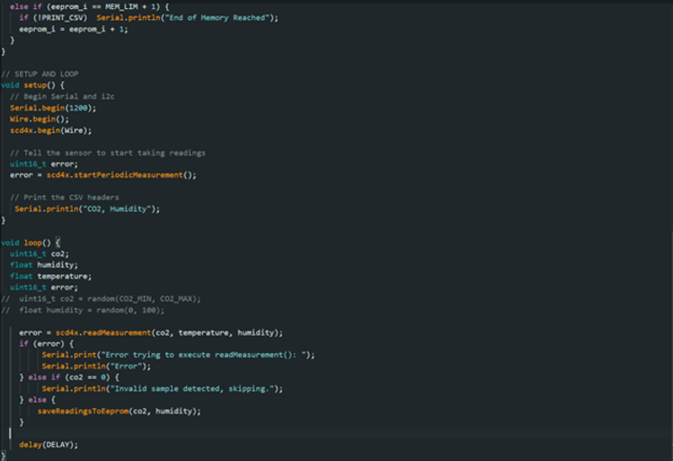

Last bit of code is to clear the eprom to prepare Genaro's sensor for launch.
Peeps for experiment
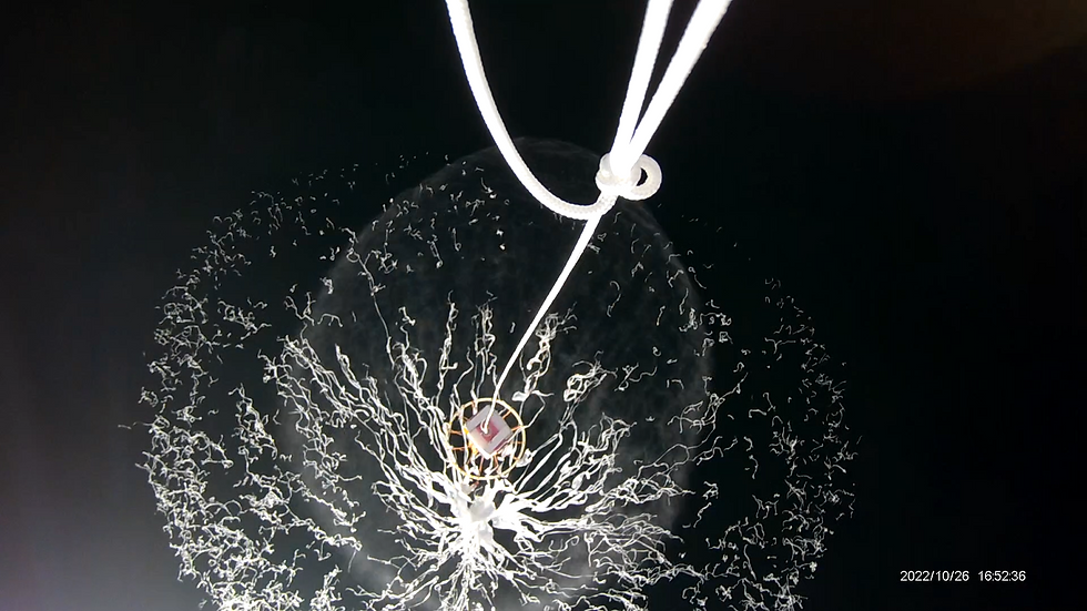
We where provided a box full of Peeps for the peep experiment for the payload.


Launch Weekend
Both teams launch their payloads! Do things go wrong?
Our team kicked back, working on our presentation for the evening and practicing it while the other team was still working on their payload. By the end of the class period, at about 16:00, we had the van packed and ready to go, and we embarked on our journey toward the hotel. There was a calm in the air that night as we slowly worked our way to 20:00, presenting and listening to presentations. The next day: I woke up and then woke up my teammate Genaro. We headed downstairs to discover that the hotel had not put out food for us and the large Answer team!
We waited quite a while for our food, and it was time to go, but there was a delay because our lunches did not arrive.
Right before they arrived, now at about 06:30, the staff of the hotel finally got the drift and set out food for the nearly 100 people that represent Answer and the balloon launch. The beginning of the day looked like an absolute flop for both the sandwich shop and the hotel we stayed at because they delivered their food late, well after we were supposed to set off.
Setting off and the trip
Once we were all loaded up and in the van, we set off toward our launch site. (CLICK THE GREEN BUTTON ^^^^^^^^ for details). During the entire two-hour drive, the other team's team lead gave my ribs a constant elbowing while trying to program their payload for the launch, a direct defiance of the professor's rules about getting them done and tested a week before the launch.
Launch
Once we arrived, we quickly got our payload connected to the balloon and ready for a successful launch.
Meetup point and a lot of waiting and looking for answers from answer
We then went to our designated launch site in Aguila, AZ. As we waited a long time and got no answers from Answer, everyone eventually got bored and tired. Finally, at about 17:00, we got a message that our balloon landed on the side of the mountain to the North-West of us. We sent a small recovery team to hike up the mountain and recover our payload. At about 18:30, the teams finally reunited with their prospective payloads. Upon inspection, our payload had hit the ground hard but mostly remained intact. The seed containment tape kept the seeds from flying everywhere. The peep, along with its measuring stick, was missing. The video card was full of videos, and at first, I was surprised we got so much video from our mission. But it turned out that the others on our team forgot to delete them, causing our recording session to end before the payload landed. Shelby's Geiger counter did not function because it did not receive power during the flight, but all other sensors, including the CO2 sensor and the RF receiver, worked!

Weeks after and Symposium
Week 12. Review data and prep for symposium
We all took a deep breath after launch; no more 10-hour days, broken or non-functioning sensors, and no more deadlines. We met our deadline and handed in our payload on Monday before the launch weekend. Today we reviewed our data under the prying eyes of our professor and Rick. Surprisingly, we had outstanding data, according to Rick, and he was suspicious about how smooth the temperature data was. Two sensors did not work properly on our payload; Shelby's Geiger counter and the accelerometer, which we used last semester. Why the Geiger counter did not work was simple, and I told Shelby that this would be a problem before the launch. He was using breadboard test wires as a permanent solution. The metal pins were smaller than the ones we would use in a more permanent solution and would slide out of the Arduino easier. Also, the wires were too short, and we did not have enough play when installing it into our payload. Both caused the issue of his sensor not getting power.
Disassembling payload and taking pictures
For our Symposium slideshow, we decided to disassemble our payload and lay out everything that was stuffed inside its tiny body. Working on the slideshow was short and sweet. We had data, and as I sat there and helped my team construct our slideshow, the other team got a grilling from Rick and Dr. Frank because they lost power in flight, worked on their stuff, such as programming during the trip to the launch site, and they missed their deadline.


Week 13
This week we worked on the slide show (below) with too much help from rick, we where able to complete the first round of practice after 3 hours. Here is the slideshow.

Week 14 (Symposium weekend)
We prepared for the Symposium by practicing our presentations in front of each other's team.
tonight we head out to symposium. The Symposium went well, I even got a few people's contacts. I really would like a job where I use my hand's on skills I gained since I was a kid.
Week 16 (End of project)
This is the final week, our final presentation will be below. The final report will probably be all the will be all the work I (Rik) have done on this page of the website. I do not think our team lead will type it, but I may be surprised.
